


KLAS por medida
Crie o seu espelho de interruptor
Pré-visualização meramente ilustrativa. As proporções seguem as medidas norte-americanas dos espelhos.
- 01 O seu tamanhoDe 1 a 6 módulos, para se adaptar à sua caixa de aparelhagem.
- 02 Cada posiçãoCombine interruptores, reguladores de intensidade, tomadas e tomadas de rede num só espelho.
- 03 Os seus acabamentosSeis acabamentos de espelho em latão maciço, além do acabamento da alavanca e do botão.
- 04 Toques finaisGrave cada etiqueta e nós fabricamos por encomenda.
Não tem a certeza do acabamento? Veja-o primeiro com a luz da sua casa.
Informação técnica
Especificações e encaixe
Tamanho do espelho para o seu design, ligações e fichas técnicas para descarregar
Especificações e encaixe
Tamanho do espelho para o seu design, ligações e fichas técnicas para descarregarO tamanho do espelho atualiza-se com o design acima. Abra qualquer aparelho para ver a ficha técnica completa ou descarregue-a em PDF para o seu eletricista. Guias de instalação: espelhos de interruptor · tomadas · reguladores de intensidade.
- Back box
- Screw holes
- 83.5 mm · 3.29 in apart (top to bottom), standard inch screws
- Standard
- North American (US & Canada), 120 V
- In the box
- Solid brass plate, devices fitted, matching screws
 KLAS
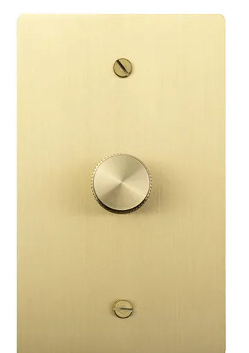
Rotary dimmers
Single-pole (grounded or basic) & 3-way · solid brass plate · knurled knob · hand-brushed, naturally unique on every plate
| Single-pole, grounded | Single-pole, basic | 3-way | |
| Use | Light controlled from one place | Light controlled from two or more places | |
| Operation | Press the knob for on/off, rotate to dim | Rotate to dim | Press the knob for on/off, rotate to dim |
| Ground wire | Yes | No (2 wires: line in, load out) | Yes (4 leads: black = common, red + red = travellers, green = ground) |
| Dimming type | Triac (forward phase) | ||
| Voltage | 110–130 V AC, 50/60 Hz | 110–120 V AC, 50/60 Hz | 108–132 V AC, 60 Hz |
| LED load | 3–150 W (dimmable LED) | 150 W dimmable LED · 150 W dimmable CFL | |
| Incandescent / halogen | 40–600 W | 40–250 W | 40–600 W |
| Rated life | 10,000+ cycles | ||
| Protection | Overheat protection · flame-retardant PC housing · 4 kV dielectric test | ||
| Neutral wire | Not required to confirm | Not required | Not required |
| Device size | to confirm | 105 × 54 × 43 mm (4.1 × 2.1 × 1.7 in), 88 g · accepts 18 AWG wire | |
| Fits | Standard 1-gang US/Canada box (per gang) | ||
| Certification | UL, US & Canada · UL file E522988 | UL, US & Canada · UL file E511941 | cULus, US & Canada · UL 1472 (solid-state dimming controls) · UL file E522988 |
| Plate | 2 mm solid brass on a 2 mm acrylic frame | ||
| In the box | Plate, dimmer fitted, matching screws | ||
Which single-pole? Both dim the same lights. The grounded dimmer also switches on and off with a press of the knob, so the light comes back at the level you left it; it suits any box, including new plastic boxes. The basic dimmer only rotates; choose it for a metal box (which grounds the plate through its screws) or to replace a dimmer in an older box with no ground wire. North American codes generally require a metal plate to be grounded; ask your electrician if unsure.

Bronze · Antique Brass · Brushed Nickel
Matte Black · Satin Brass · White
Plate sizes
* 5- and 6-gang estimated (+45 mm per gang) — to confirm
| Gangs | 1 | 2 | 3 | 4 | 5 | 6 |
|---|---|---|---|---|---|---|
| Width (mm) | 72 | 120 | 165 | 210 | 255* | 300* |
| Width (in) | 2.83 | 4.72 | 6.50 | 8.27 | 10.04* | 11.81* |
| Height | 120 mm · 4.72 in (all sizes) | |||||
| Screw holes | 83.5 mm · 3.29 in apart (top to bottom) · standard inch screws | |||||
Wiring · single-pole
Basic dimmer: same, without the ground wire to the dimmer. Ground the light fitting as normal.
Wiring · 3-way dimmer
Pair the 3-way dimmer with a KLAS 3-way toggle at the other location. For three or more locations, add a 4-way toggle in between. Use one dimmer per light circuit.
KLAS0–10V rotary dimmer · low voltage
For LED lights with 0–10V or 1–10V dimmable drivers · solid brass plate · knurled knob
| Type | 0–10V / 1–10V rotary dimmer (control signal only) |
|---|---|
| Works with | LED fittings with a 0–10V or 1–10V dimmable driver: downlights, track lights, wall washers and similar |
| Control signal | 0.5–10 V DC · up to 40 mA dimming current |
| Load | Up to 150 W of LED, through compatible drivers |
| Dimming | Smooth, stepless, 5–100% · no flicker or hum |
| On / off | Does not switch power. Pair it with a toggle (or the driver's own switching) to turn the light off. |
| Wires | Brown = DIM+ · Blue = DIM– · 13 in (33 cm) leads |
| Device size | 0.9 × 1.3 × 1.3 in (23 × 33 × 33 mm), including knob |
| Operating temperature | –15 °C to +50 °C (5 °F to 122 °F) |
| Mounting | Recessed in a standard box, or surface-mounted |
| Certification | to confirm |
| Plate | 2 mm solid brass on a 2 mm acrylic frame · sizes as for all KLAS plates (1-gang 72 × 120 mm, 2.83 × 4.72 in) |
| In the box | Plate, dimmer fitted, matching screws |
Bronze · Antique Brass · Brushed Nickel
Matte Black · Satin Brass · White
Wiring
Important
- Never connect to mains power. It connects only to the driver's dimming terminals.
- Mains power goes to the LED driver, switched by a separate toggle if needed.
- In a multi-gang plate with mains devices, keep low-voltage and mains wiring separated in the box (a divider is usually required by code).
- Check the driver is 0–10V or 1–10V dimmable; standard (triac) LED drivers won't work with it.
KLASFan speed switch
Rotary speed control for ceiling paddle fans · solid brass plate · knurled knob
| Rating | 120 V AC, 60 Hz |
|---|---|
| For | Ceiling paddle fans only · one fan per control |
| Control | Rotary, off and variable speed |
| Wires | Black = hot · White = to fan · Green = ground · copper wire only |
| Fan with a light | The light needs its own separate wiring and switch; this control runs the fan only |
| Smart fans | Not compatible with fans that have built-in smart or remote systems. Replaces a standard stepped or stepless control. |
| Fits | Standard 1-gang US/Canada box (per gang) |
| Certification | UL, US & Canada · fan-speed controls · UL file E312727 |
| Plate | 2 mm solid brass on a 2 mm acrylic frame · sizes as for all KLAS plates (1-gang 72 × 120 mm, 2.83 × 4.72 in) |
| In the box | Plate, control fitted, matching screws |
Bronze · Antique Brass · Brushed Nickel
Matte Black · Satin Brass · White
Wiring

Do not use for
- Outlets (receptacles)
- Lights, including fluorescent
- Transformers, motor appliances, or anything supplied by a transformer
- More than one fan
Using it
- Turn the dial about half a turn to start the fan (the motor needs a burst of power to start), then set the speed you want.
- If the speed suddenly drops, the dial is between steps; turn it a little further.
Installation
Turn off the breaker first. Install by a licensed electrician, following the NEC / CEC and local codes. If the wall box has no ground, cap or remove the green wire as the code allows (NEC 404.9(B), formerly 380-9(b)).
KLAS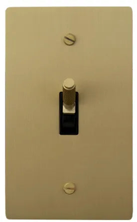
Toggle switch
Solid brass plate · knurled brass lever · hand-brushed, naturally unique on every plate
| Single-pole & 3-way | 4-way | |
| Use | One location (single-pole) or two locations (3-way) | Third or more location, fitted between two 3-ways |
| Voltage | 120 V AC | 110–120 V AC |
| Current | 15 A to confirm | 15 A |
| Neutral wire | Not required | |
| Fits | Standard 1-gang US/Canada box (per gang) | |
| Certification | cULus Listed, US & Canada · UL 20 / CSA C22.2 No. 111 (general-use snap switches) · UL file E313169 catalogue no. to confirm | |
| Switch body | Black or white (ivory to confirm) | |
| Plate | 2 mm solid brass on a 2 mm acrylic frame to confirm | |
| In the box | Plate, switch fitted, matching screws | |

Switch body options shown on satin brass
Plate sizes
| Gangs | 1 | 2 | 3 | 4 | 5 | 6 |
|---|---|---|---|---|---|---|
| Width (mm) | 72 | 120 | 165 | 210 | 255* | 300* |
| Width (in) | 2.83 | 4.72 | 6.50 | 8.27 | 10.04* | 11.81* |
| Height | 120 mm · 4.72 in · screw holes 83.5 mm (3.29 in) apart, inch screws | |||||
Wiring · single-pole
Wiring · 3 or more locations
Two locations: 3-way + 3-way. Each extra location adds one 4-way in between. Ground to every switch.
KLASOutlets
Tamper-resistant receptacles in a solid brass plate · hand-brushed, naturally unique on every plate

Duplex · GFCI · USB-A + USB-C, shown on satin brass. Dual USB-C below
| Duplex outlet | GFCI outlet | USB outlet | Dual USB-C outlet | |
| Use | Everyday sockets | Near water: kitchens, bathrooms, laundry, outdoors. Test / reset buttons | Two sockets plus built-in charging | Two sockets plus two fast-charging USB-C ports |
| Rating | 15 A or 20 A · 120 V AC. The 20 A version has a T-shaped neutral slot and must be on a 20 A circuit; a 15 A outlet is allowed on a 20 A circuit when there are two or more outlets on it. Dual USB-C: 15 A 20 A version to confirm | |||
| Tamper-resistant | Yes (TR), as required in US homes | |||
| USB ports | None | None | 1 × USB-A, 1 × USB-C · output (W) to confirm | 2 × USB-C · output (W) to confirm |
| Fits | Standard 1-gang US/Canada box (per gang) GFCI/USB depth to confirm | |||
| Certification | UL, US & Canada · UL 498 / CSA C22.2 No. 42 (receptacles) · UL file E481372 catalogue no. per device to confirm; GFCI also needs UL 943 | |||
| Device colour | White, black or ivory | |||
| Plate | 2 mm solid brass on a 2 mm acrylic frame | |||
| In the box | Plate, outlet fitted, matching screws | |||

Device colours: white · black · ivory

Dual USB-C outlet · two sockets + two USB-C ports, white or black
Plate sizes
| Gangs | 1 | 2 | 3 | 4 | 5 | 6 |
|---|---|---|---|---|---|---|
| Width (mm) | 72 | 120 | 165 | 210 | 255* | 300* |
| Width (in) | 2.83 | 4.72 | 6.50 | 8.27 | 10.04* | 11.81* |
| Height | 120 mm · 4.72 in · screw holes 83.5 mm (3.29 in) apart, inch screws | |||||
Wiring
GFCI: incoming power to LINE terminals; LOAD terminals protect outlets further down the circuit.
Installation
Install by a licensed electrician with the power off at the breaker, following local codes. Press TEST then RESET on a GFCI after installation, and monthly.
KLAS
Data & phone ports
CAT 6 network and RJ11 telephone jacks in a solid brass plate · hand-brushed, naturally unique on every plate
| CAT 6 data port | RJ11 telephone port | |
| Use | Wired internet: TVs, computers, game consoles, Wi-Fi access points | Landline phone, fax, alarm or DSL line |
| Category | CAT 6 · up to 1 Gb/s at 100 m, 10 Gb/s on shorter runs (about 55 m) | CAT 3 voice grade |
| Jack | RJ45 (8 contacts) termination type to confirm | RJ11 4 or 2 contacts to confirm |
| Wiring standard | T568B or T568A (match the other end of the cable) | USOC, line 1 on the centre pair |
| Power | Low voltage only, no mains connection | |
| Fits | North American standard: 1-gang box or low-voltage mounting bracket (per port). Back box sold separately | |
| Certification | to confirm | |
| Insert colour | White or black | |
| Plate | 2 mm solid brass on a 2 mm acrylic frame | |
| In the box | Plate, jack fitted, matching screws. Cable not included | |

Antique Brass

Bronze

Brushed Nickel

Satin Brass

Matte Black
Shown with the black insert. Mix with switches and outlets on one plate in the designer.
Plate sizes
| Gangs | 1 | 2 | 3 | 4 | 5 | 6 |
|---|---|---|---|---|---|---|
| Width (mm) | 72 | 120 | 165 | 210 | 255* | 300* |
| Width (in) | 2.83 | 4.72 | 6.50 | 8.27 | 10.04* | 11.81* |
| Height | 120 mm · 4.72 in · screw holes 83.5 mm (3.29 in) apart, inch screws | |||||
Wiring · CAT 6 (T568B)
T568A swaps the orange and green pairs. Use the same standard at both ends. Keep the twists to within 13 mm (½ in) of the jack.
Wiring · RJ11 telephone
Older cable may use blue / white-blue for line 1 and orange / white-orange for line 2.
Installation
Install by a qualified installer, following local codes. Keep data and phone cable away from mains wiring: do not share a box with power cables unless a barrier separates them (NEC 800.133). On a plate that also has switches or outlets, the data or phone position needs its own box section or bracket. Test each CAT 6 run with a cable tester after fitting.
InstalaçãoInstalar o seu espelho
Quatro passos, um desenho e os guias de ligação completos de cada aparelho
Instalar o seu espelho
Quatro passos, um desenho e os guias de ligação completos de cada aparelhoO seu espelho chega com os aparelhos já montados. As ligações à rede elétrica devem ser feitas por um eletricista certificado.
- 01Desligue e testeDesligue o disjuntor do circuito e verifique os fios na caixa com um detetor de tensão.
- 02Ligue os fiosLigue os fios de cada aparelho à instalação da casa com ligadores, como indicado no guia desse aparelho. Ligue todos os aparelhos à terra.
- 03Fixe o espelhoDobre os fios para dentro da caixa, nivele o espelho e fixe-o com os dois parafusos fornecidos por módulo. Aperte de forma uniforme, sem apertar demasiado.
- 04Ligue a corrente e testeVolte a ligar o disjuntor e teste todas as posições. Num GFCI, prima TEST e depois RESET.
Full guides with wiring tables
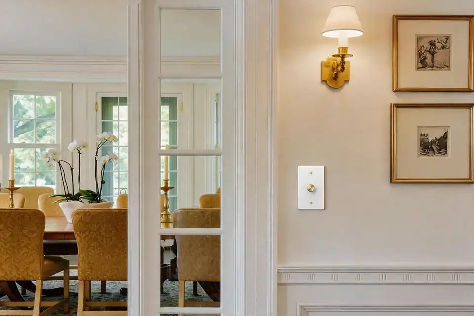
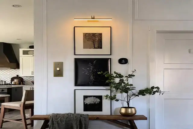
Veja o acabamento em contexto
Divisões reais, condições de luz reais
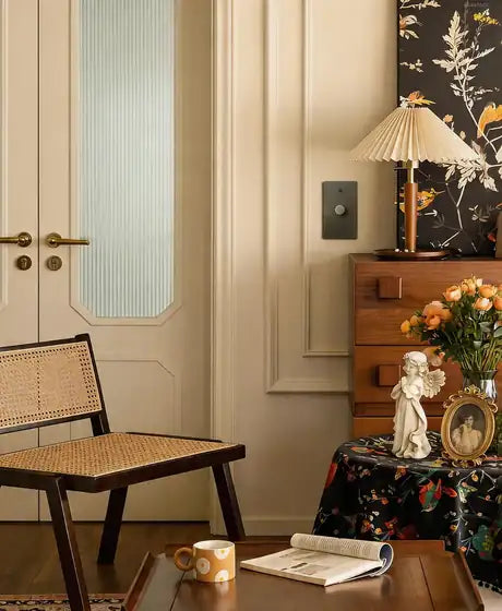

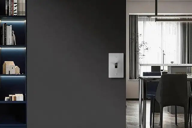
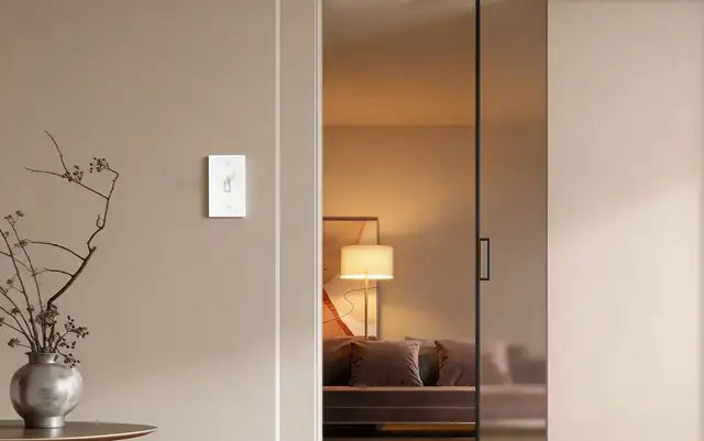
O que dizem os nossos clientes
- GWGord W.Verified BuyerReviewingKLAS / Brass Mixed Dimmer Switch (3-Gang)I recommend this productRated 5 out of 5 stars3 hours agoDimmer switches
Great
Product
- JHJustin H.Verified BuyerReviewingKLAS / Brass Light Switch (1-Gang)I recommend this productRated 5 out of 5 starsYesterdaySeemingly small upgrade with a big impact
Outfitted our entire house in these in a recent remodel. They get noticed and complemented often. Love them.
- AKAndrea K.Verified BuyerReviewingKLAS / Brass Mixed Dimmer Switch Outlet (2-Gang)I recommend this productRated 5 out of 5 stars1 month agoLuxury look and feel
I was very impressed with the product. It is a showpiece in my home that attracts a lot of compliments. The brass construction is solid and weighty, and the switch itself moves like a high quality stereo equipment knob. I will be buying more of these!
- JSJohn S.Verified BuyerReviewingKLAS / Brass Light Switch (3-Gang)I recommend this productRated 5 out of 5 stars1 month agoClassic Look
Excellent switches for my man cave and garage
- MSMary S.Verified BuyerReviewingKLAS / Brass Rotary Dimmer Switch (1-Gang)I recommend this productRated 5 out of 5 stars2 months agoAll in the details
These switches are the perfect finishing detail on my bathroom remodel. Smooth operation on the dimmers, Someone called them a tactile experience and I agree. Quality craftsmanship.
Perguntas e respostas
Quanto tempo demora um espelho personalizado?
Os espelhos personalizados são fabricados por encomenda. Os prazos variam consoante o design; contacte-nos se precisar de uma data de entrega.
Para que norma de instalação elétrica é este produto?
Os espelhos KLAS são fabricados para caixas de aparelhagem norte-americanas. Se precisar do formato do Reino Unido ou da UE, contacte-nos antes de encomendar.
Como é instalado?
O seu espelho chega com os aparelhos já montados. Um eletricista liga os fios e, depois, dois parafusos fixam o espelho à caixa de aparelhagem. Guias passo a passo com tabelas de ligações: espelhos de interruptor, tomadas e reguladores de intensidade.
Posso devolver um espelho personalizado?
Os artigos personalizados e fabricados por encomenda não admitem devolução. Consulte a nossa política de reembolso.
Posso ver o acabamento antes de encomendar?
Sim. Encomende uma amostra de acabamento KLAS em qualquer acabamento, ou o conjunto completo de seis, e veja-a com a luz da sua casa antes de criar o seu espelho.